Vibration Monitoring
1. Introduction
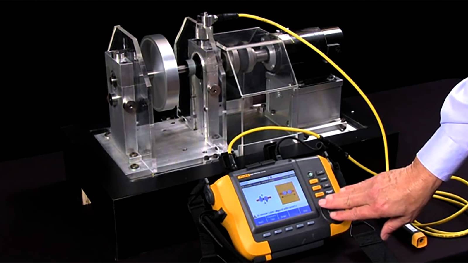
Vibration monitoring is a predictive maintenance technique that measures and analyzes the mechanical vibration signatures of rotating and reciprocating machinery to detect developing faults before they fail. Rather than waiting for a breakdown (reactive maintenance) or servicing equipment on a fixed schedule regardless of condition (preventive maintenance), vibration monitoring supports condition-based maintenance (CBM): interventions are triggered by the actual health of the asset.
It is widely deployed across manufacturing plants, power generation facilities, oil and gas installations, and transportation systems, wherever pumps, motors, fans, compressors, turbines, and gearboxes operate continuously under load.
2. Why Machines Vibrate
Every piece of rotating machinery vibrates to some degree. Vibration monitoring is concerned with detecting abnormal vibration patterns that indicate a mechanical fault. Common root causes include:
|
Fault Type |
Typical Cause |
Vibration Signature |
|
Imbalance |
Uneven mass distribution on a rotor |
Dominant peak at 1× running speed (1×RPM) |
|
Misalignment |
Shaft/coupling offset between driver and driven equipment |
Peaks at 1×, 2×, and sometimes 3× running speed |
|
Bearing wear/defects |
Spalling, pitting, or lubrication failure |
High-frequency peaks at bearing defect frequencies (BPFO, BPFI, BSF, FTF) |
|
Looseness |
Loose foundation bolts, worn housings |
Multiple harmonics of running speed, often with a "flat noise floor" |
|
Gear defects |
Worn or chipped gear teeth |
Gear mesh frequency (GMF) with sidebands |
|
Resonance |
Operating speed coincides with a natural frequency |
Amplified vibration at a specific frequency, independent of load |
|
Cavitation (pumps) |
Vapor bubble formation/collapse |
Broadband, random high-frequency noise |
3. Key Measurement Parameters
Vibration is typically characterized using three physical parameters, each suited to a different frequency range and fault type:
- Displacement (µm or mils): The physical distance a point moves from its rest position. Best for detecting low-frequency issues in slow-speed machinery (e.g., below ~600 RPM) and is commonly measured with non-contact proximity probes on fluid-film bearings.
- Velocity (mm/s or in/s): The rate of change of displacement. This is the most widely used parameter for overall machine health assessment in the 10 Hz–1 kHz range, as it correlates well with fatigue and mechanical stress. Most vibration standards (e.g., ISO 10816/20816) are expressed in velocity terms.
- Acceleration (g or m/s²): The rate of change of velocity. Most sensitive to high-frequency phenomena such as bearing defects and gear mesh issues (above ~1 kHz), typically captured via accelerometers.
RMS (Root Mean Square) values are generally used for overall vibration severity, since they represent the energy content of the signal, whereas peak and peak-to-peak values are used for detecting transient shocks or impacts.
4. Sensors and Data Acquisition
|
Sensor Type |
Measures |
Typical Use Case |
|
Piezoelectric accelerometer |
Acceleration |
General-purpose, most common sensor for CBM programs |
|
Eddy-current (proximity) probe |
Displacement |
Shaft relative motion on fluid-film/journal bearings, turbomachinery |
|
Velocity transducer (seismic) |
Velocity |
Low-frequency structural monitoring |
|
Laser vibrometer |
Velocity/displacement |
Non-contact measurement on inaccessible or delicate components |
|
MEMS sensors / wireless IIoT nodes |
Acceleration |
Low-cost, continuous online monitoring across many assets |
Data can be collected via:
- Route-based (portable) monitoring — a technician periodically collects readings using a handheld data collector, suited to less critical assets.
- Online/continuous monitoring — permanently installed sensors feed data to a monitoring system in real time, used for critical or high-risk machinery where failure has severe safety, environmental, or production consequences.
5. Signal Analysis Techniques
Raw vibration signals are processed to extract diagnostic information:
- Time-Domain Analysis — Examines the raw waveform for amplitude, shape, and transient events (e.g., impacts, truncation from rubbing).
- Frequency-Domain Analysis (FFT/Spectrum Analysis) — Converts the time-domain signal into a frequency spectrum using the Fast Fourier Transform, allowing specific fault frequencies (1×RPM, bearing frequencies, gear mesh frequencies) to be isolated and tracked.
- Envelope Analysis (Demodulation) — Filters and demodulates high-frequency resonance signals to reveal repetitive impacting characteristics of early-stage bearing and gear defects, often before they are visible in a standard spectrum.
- Trend Analysis — Tracks overall vibration severity over time against a baseline to identify gradual degradation.
- Phase Analysis — Compares the phase relationship between measurement points to distinguish between imbalance, misalignment, and looseness.
- Order Tracking — Used on variable-speed machinery, normalizing frequency data to shaft speed rather than absolute frequency.
6. Standards and Severity Thresholds
Vibration severity is typically benchmarked against international standards, most notably:
- ISO 20816 (replacing ISO 10816): Evaluation of machine vibration by measurements on non-rotating parts, with severity zones (A–D) based on machine class, power rating, and support type.
- ISO 13373: Condition monitoring and diagnostics of machines — vibration condition monitoring procedures.
- API 670: Machinery protection systems, commonly applied to critical turbomachinery in oil & gas.
- ISO 18436: Requirements for the qualification and certification of vibration analysis personnel (Category I–IV).
Typical zone classification (illustrative, per ISO 20816-3 for medium-sized machines):
|
Zone |
Condition |
Typical Velocity RMS Range |
|
A |
Newly commissioned machine |
Very low (baseline) |
|
B |
Acceptable for unrestricted long-term operation |
Low |
|
C |
Unsatisfactory for long-term operation |
Elevated — plan maintenance |
|
D |
Vibration severe enough to cause damage |
High — immediate action required |
(Exact thresholds vary by machine class, power, and mounting type — always refer to the applicable ISO 20816 part.)
7. A Typical Monitoring Workflow
- Asset Criticality Ranking — Identify which machines warrant online monitoring vs. periodic route-based checks, based on failure consequence (safety, production loss, repair cost).
- Baseline Establishment — Record vibration signatures under known-good conditions to serve as the reference for future comparison.
- Data Collection — Periodic or continuous acquisition of vibration data at defined measurement points (typically bearing housings, in horizontal, vertical, and axial directions).
- Alarm Setting — Configure alert and danger thresholds (often per ISO 20816 zones or statistically derived from historical trends).
- Diagnosis — When a threshold is breached, spectral and envelope analysis is used to pinpoint the fault type and its likely root cause.
- Maintenance Action — Schedule targeted repair (e.g., re-alignment, bearing replacement, balancing) during a planned outage rather than reacting to an unplanned failure.
- Verification — Post-repair measurements confirm the fault has been resolved and establish a new baseline.
8. Business Benefits
- Reduced unplanned downtime by catching faults at an early, low-cost repair stage.
- Extended equipment lifespan through timely correction of damaging conditions (misalignment, imbalance) before secondary damage occurs.
- Lower maintenance costs by shifting from time-based to condition-based interventions, avoiding both premature part replacement and catastrophic failure.
- Improved safety by identifying conditions that could otherwise lead to sudden equipment failure or hazardous incidents.
- Better production planning since required repairs can be scheduled around production needs instead of being forced by breakdowns.
9. Typical Applications by Industry
- Manufacturing: Motors, fans, pumps, gearboxes, conveyor systems.
- Power Generation: Turbines, generators, boiler feed pumps.
- Oil & Gas: Compressors, turbomachinery trains, critical pumps (often per API 670 protection systems).
- Transportation: Rail bogies, marine propulsion shafting, aircraft ground support equipment.
10. Summary
Vibration monitoring converts the mechanical "signature" of a machine into actionable diagnostic data, enabling maintenance teams to move from reactive or purely time-based servicing to a condition-based strategy. By combining the right sensor technology, measurement parameters, and analysis techniques — benchmarked against recognized standards such as ISO 20816 — organizations can detect faults such as imbalance, misalignment, bearing wear, and looseness well before they escalate into costly failures, improving both reliability and safety across industrial operations.
Topics